7.2. Motor Configuration
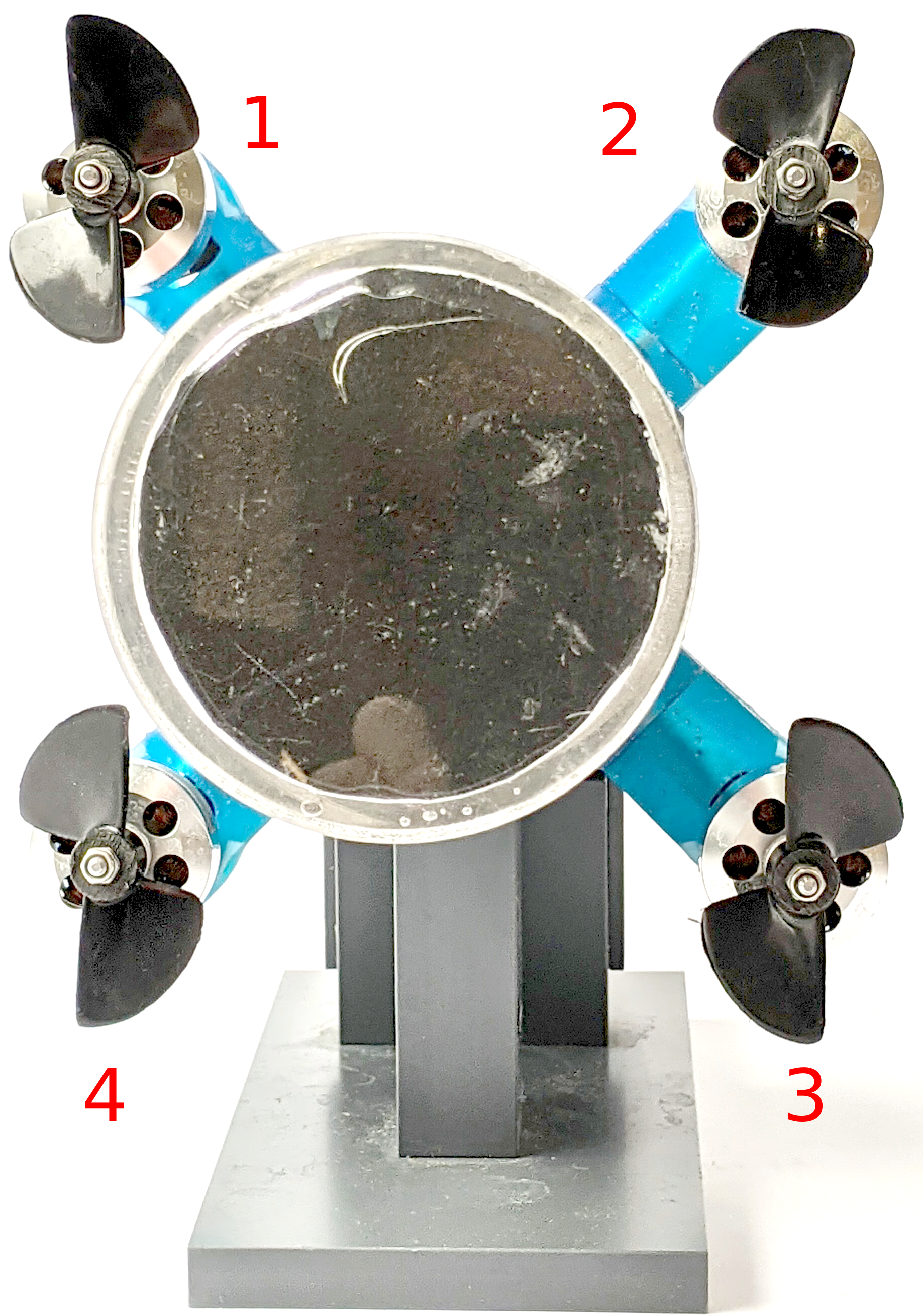
The following image depicts the thruster configuration. The numbers correspond to the FCU’s PWM outputs. Make sure the propellers are mounted correctly since there are two clockwise and two counterclockwise propellers.

Fig. 7.1 Motor and propeller configuration.
To avoid confusion, the order of the three motor/ESC wires should be black, red, yellow from front to rear. If the ESC or motor has other colors for its wires make sure the motor turns in positive direction (right hand rule with axis parallel to the vehicle’s x-axis 😉) for positive setpoints.
To test this you can use the motor_test command in the FCU’s shell (you can access the shell via the debug port or via QGroundControl’s MAVLink Console). For details see the PX4 documentation.
Attention
Since we use the motors in reversible mode the parameter -p 50 corresponds to a stopped motor. 0 corresponds to full throttle backward and 100 corresponds to full throttle forward.
To let the first motor turn for a second you can enter for example this:
$ motor_test test -p 60 -m 1 -t 1