PX4 Setup
Note
PX4 is currently used for the real robot exclusively and is not part of the simulation. Skip this section if you are not preparing for the lab experiments. If in doubt ask your supervisor.
Building the Firmware
If PX4 is used in combination with the onboard computer, make sure the firmware running on the FCU was built with RTPS support.
A tested PX4-Version is the commit 45b390b0bf.
$ git clone https://github.com/PX4/PX4-Autopilot.git \
&& cd PX4-Autopilot \
&& git checkout 45b390b0bf \
&& git submodule update --init --recursive
For this version the RTPS support is not enabled by default for the fmu-v4 target (i.e. the PixRacer). One has to modify the file boards/px4/fmu-v4/default.px4board and add the line
CONFIG_MODULES_MICRODDS_CLIENT=y
Also modify the autostart-line in src/modules/microdds_client/module.yaml if you want to have a namespace prepended to the topic names
set XRCE_DDS_ARGS "-t serial -d ${SERIAL_DEV} -b p:${BAUD_PARAM} -n uuv00"
Also a good starting point for a minimal set of bridged topics defined in src/modules/microdds_client/dds_topics.yaml is
 1publications:
 2
 3  - topic: /fmu/out/failsafe_flags
 4    type: px4_msgs::msg::FailsafeFlags
 5
 6  - topic: /fmu/out/sensor_combined
 7    type: px4_msgs::msg::SensorCombined
 8
 9  - topic: /fmu/out/timesync_status
10    type: px4_msgs::msg::TimesyncStatus
11
12  - topic: /fmu/out/vehicle_odometry
13    type: px4_msgs::msg::VehicleOdometry
14
15subscriptions:
16
17  - topic: /fmu/in/vehicle_visual_odometry
18    type: px4_msgs::msg::VehicleOdometry
Build the firmware
make px4_fmu-v4
./Tools/docker_run.sh 'make px4_fmu-v4'
make px4_fmu-v6c
./Tools/docker_run.sh 'make px4_fmu-v6c'
Normally, the microdds_client is started automatically, and no further actions are required. Anyhow, to manually start the microdds_client, go to the nsh terminal and run
$ microdds_client start -t serial -d /dev/ttyS2 -b 921600 -n uuv00
Configure the Firmware
Attention
Make sure you disable the GPS completely by changing its control mode parameter. Otherwise the the vision will be taken as odometry data instead of absolute positions.
Set XRCE_DDS_0_CFG to TELEM2, i.e. 102. If you want to, you can change the baudrate of TELEM2 at SER_TEL2_BAUD. But the default of 921600 should be just fine.
Note
Make sure you disable all MAVLink interfaces on TELEM2.
Install px4_msgs
Hint
Building and rebuilding px4_msgs takes very long, especially on the Raspberry Pi. Therefore, it is recommended to have an underlying workspace for packages that we are not modifying regularly.
A commit that is tested to be working with the above-mentioned version of PX4 is 8a7f3da.
Clone it into the ROS workspace
$ git clone https://github.com/PX4/px4_msgs.git \
&& cd px4_msgs \
&& checkout 8a7f3da
Install Micro-XRCE-DDS-Agent
Clone and build the agent
$ cd ~/ros2_underlay/src \
&& git clone https://github.com/eProsima/Micro-XRCE-DDS-Agent.git \
&& build_underlay
Running the Micro-XRCE-DDS-Agent
Replace device and baudrate with the correct values.
$ MicroXRCEAgent serial --dev /dev/fcu_data -b 921600
If the setup is working, ros2 topic list should show the FMUs in and out topics.
/uuv00/fmu/in/obstacle_distance [px4_msgs/msg/ObstacleDistance]
/uuv00/fmu/in/offboard_control_mode [px4_msgs/msg/OffboardControlMode]
/uuv00/fmu/in/onboard_computer_status [px4_msgs/msg/OnboardComputerStatus]
/uuv00/fmu/in/sensor_optical_flow [px4_msgs/msg/SensorOpticalFlow]
/uuv00/fmu/in/telemetry_status [px4_msgs/msg/TelemetryStatus]
/uuv00/fmu/in/trajectory_setpoint [px4_msgs/msg/TrajectorySetpoint]
/uuv00/fmu/in/vehicle_attitude_setpoint [px4_msgs/msg/VehicleAttitudeSetpoint]
/uuv00/fmu/in/vehicle_command [px4_msgs/msg/VehicleCommand]
/uuv00/fmu/in/vehicle_mocap_odometry [px4_msgs/msg/VehicleOdometry]
/uuv00/fmu/in/vehicle_rates_setpoint [px4_msgs/msg/VehicleRatesSetpoint]
/uuv00/fmu/in/vehicle_trajectory_bezier [px4_msgs/msg/VehicleTrajectoryBezier]
/uuv00/fmu/in/vehicle_trajectory_waypoint [px4_msgs/msg/VehicleTrajectoryWaypoint]
/uuv00/fmu/in/vehicle_visual_odometry [px4_msgs/msg/VehicleOdometry]
/uuv00/fmu/out/failsafe_flags [px4_msgs/msg/FailsafeFlags]
/uuv00/fmu/out/sensor_combined [px4_msgs/msg/SensorCombined]
/uuv00/fmu/out/timesync_status [px4_msgs/msg/TimesyncStatus]
/uuv00/fmu/out/vehicle_attitude [px4_msgs/msg/VehicleAttitude]
/uuv00/fmu/out/vehicle_control_mode [px4_msgs/msg/VehicleControlMode]
/uuv00/fmu/out/vehicle_local_position [px4_msgs/msg/VehicleLocalPosition]
/uuv00/fmu/out/vehicle_odometry [px4_msgs/msg/VehicleOdometry]
/uuv00/fmu/out/vehicle_status [px4_msgs/msg/VehicleStatus]
MAVLink Router / QGroundControl
QGroundControl is very useful to set parameters and to calibrate the sensors of the FCU. The MAVLink Router is needed to connect to the QGroundControl App on your (Desktop) computer.
If not installed on the Raspberry Pi of the vehicle:
$ git clone https://github.com/mavlink-router/mavlink-router.git \
&& cd mavlink-router \
&& git checkout 3b48da1
Build and install the code following the official instructions.
The configuration file is at /etc/mavlink-router/main.conf and can contain the following:
[General]

[UartEndpoint USB]

# Path to UART device. like `/dev/ttyS0`
# Mandatory, no default value
Device =/dev/ttyACM0
Baud = 921600

[UdpEndpoint hippo-celsius]
Mode = normal
Address = 192.168.0.115
Port = 14550
Adjust the address to your ground control computer’s IP address if you are not using the hippo-celsius Desktop computer within the lab.
Attention
The UDP Endpoint currently does not work for the very first connection. Manual way of connecting via TCP is described below.
Run the router via
$ mavlink-routerd
Manual Connection to QGroundControl
First, the mavlink router needs to be running on the vehicle.
In QGC, click on the top left corner icon -> Application settings -> Comm links -> Add
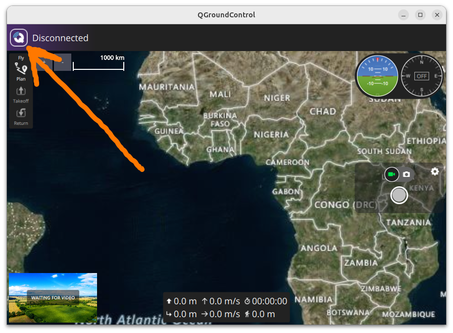
Fig. 2 Where to find the settings.
Add a TCP comm link with standard settings. Add the vehicle’s name and IP address. It should look like this:
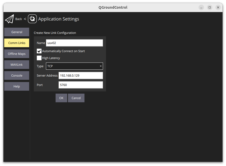
Fig. 3 TCP comm link settings for UUV02.
Now, you should be able to connect. The vehicle setup page should open:
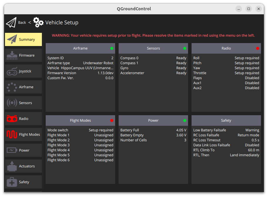
Note
After this first manual connection via TCP from your ground control station to the vehicle, the UDP endpoint should/will start working.
Sensor Calibration
You might have to calibrate the vehicle’s sensors. Click on Sensors:
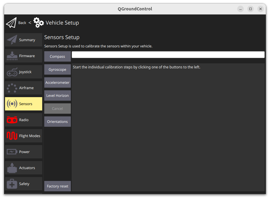
and follow the instructions.