Usage
Run the xyz Setup
On the Raspberry Pi on the gantry ( ssh pi@gantry.local ), run:
$ ros2 launch gantry xyz_motors.launch.py
This will start the three motors for the x-, y-, and z-axis, respectively.
The configuration files for the motors are found in gantry/config/motor_<axis_name>.yaml.
If you encounter any error messages, e.g. time outs, just keep repeating the launch command… a reboot of the Raspberry Pi ( sudo reboot ) or a reboot of the entire setup (see below) can help, too. Eventually, all 3 motors should work. TODO: this needs to be fixed.
Example for timeout errror for x-axis motor:
pi@gantry ~
$ ros2 launch gantry xyz_motors.launch.py
[INFO] [launch]: All log files can be found below /home/pi/.ros/log/2025-06-11-13-28-20-755904-gantry-5649
[INFO] [launch]: Default logging verbosity is set to INFO
[INFO] [xyz_motors-1]: process started with pid [5687]
[xyz_motors-1] [INFO] [1749641301.578167645] [xyz_motor]: Created x axis motor.
[xyz_motors-1] [INFO] [1749641301.578849939] [xyz_motor]: Created y axis motor.
[xyz_motors-1] [INFO] [1749641301.579263456] [xyz_motor]: Created z axis motor.
[xyz_motors-1] [ERROR] [1749641301.944969580] [motor_interface]: Read timed out.
[xyz_motors-1] [FATAL] [1749641301.945241672] [gantry.motor_x]: Could not read motor position. Are all wires connected properly? Is the motor powered (relay box)?
[xyz_motors-1] [FATAL] [1749641301.945584319] [gantry.motor_x]: Node will be inactive.
[xyz_motors-1] [INFO] [1749641302.049688477] [gantry.motor_y]: Initialized.
[xyz_motors-1] [INFO] [1749641302.053621334] [gantry.motor_z]: Initialized.
Home the Motors
Important
Always make sure that the motors are homed before sending any setpoints!
Note
The motor position is stored inside the motion controller and not inside any code running on the Raspberry Pi or any ROS node. Relaunching any node does not make it necessary to rerun the homing procedure 🥳.
Run the GUI (see Run (and use) the GUI)
Press the “Go Home” Button for each axis. The motors should start homing.
Once each motor has reached its lower limit, press “Set Position” for each axis.
Move the motors to the home position.
The motors provide a service to move to the home position.
$ ros2 service call /gantry/motor_x/start_homing std_srvs/srv/Trigger{}
$ ros2 service call /gantry/motor_y/start_homing std_srvs/srv/Trigger {}
$ ros2 service call /gantry/motor_z/start_homing std_srvs/srv/Trigger {}
Set the current position. Usually this will be 0 but we can also specify arbitrary values either in motor dimensions (i.e. increments) or in physical dimensions ([m]).
$ ros2 service call /gantry/motor_x/set_home_position gantry_msgs/srv/SetHomePosition {}
$ ros2 service call /gantry/motor_y/set_home_position gantry_msgs/srv/SetHomePosition {}
$ ros2 service call /gantry/motor_z/set_home_position gantry_msgs/srv/SetHomePosition {}
Todo
Add an example for non zero values
Smooth Accelerations in Position Mode
The maximum acceleration can be set via the ~/set_max_accel service.
If the maximum acceleration is higher than what the motor can acutally achieve (it has to move quite a bit of mass) it will overshoot the target position.
For smoother accelerations we can reduce the acceleration to a smaller value.
To get the currently set value run
$ ros2 service call /gantry_motor_x/get_max_accel gantry_msgs/srv/GetFloatDrive {}
$ ros2 service call /gantry_motor_y/get_max_accel gantry_msgs/srv/GetFloatDrive {}
$ ros2 service call /gantry_motor_z/get_max_accel gantry_msgs/srv/GetFloatDrive {}
To set a new value run
$ ros2 service call /gantry_motor_x/set_max_accel gantry_msgs/srv/SetFloatDrive '{motorside_value: 500}'
$ ros2 service call /gantry_motor_y/set_max_accel gantry_msgs/srv/SetFloatDrive '{motorside_value: 500}'
$ ros2 service call /gantry_motor_z/set_max_accel gantry_msgs/srv/SetFloatDrive '{motorside_value: 500}'
Note
We could also set the driveside_value in SI units instead of value in motor dimensions.
Limit the Motor Velocity in Position Mode
This is equivalent to acceleration limit settings, but the service names are
~/get_max_speed~/set_max_speed
Run a Single Motor
$ ros2 run gantry single_motor --ros-args \
--params-file <path_to_config_file> \
-r __node:=<motor_name> \
-r __ns:=<namespace>
Note
The path to the config file can be relative or absolute.
Attention
Keep in mind that namespaces have to start with a leading /.
Setting the node name and the namespace is optional but recommended.
- Example
Assuming we are inside the
gantrypackage directory, we can directly run$ ros2 run gantry single_motor --ros-args \ --params-file config/motor_x.yaml \ -r __node:=single_x \ -r __ns:=gantry
Run (and use) the GUI
On any computer with a graphical interface (i.e. not the Raspberry Pi via SSH), for example your laptop, run our GUI:
$ ros2 run gantry_gui manual_control
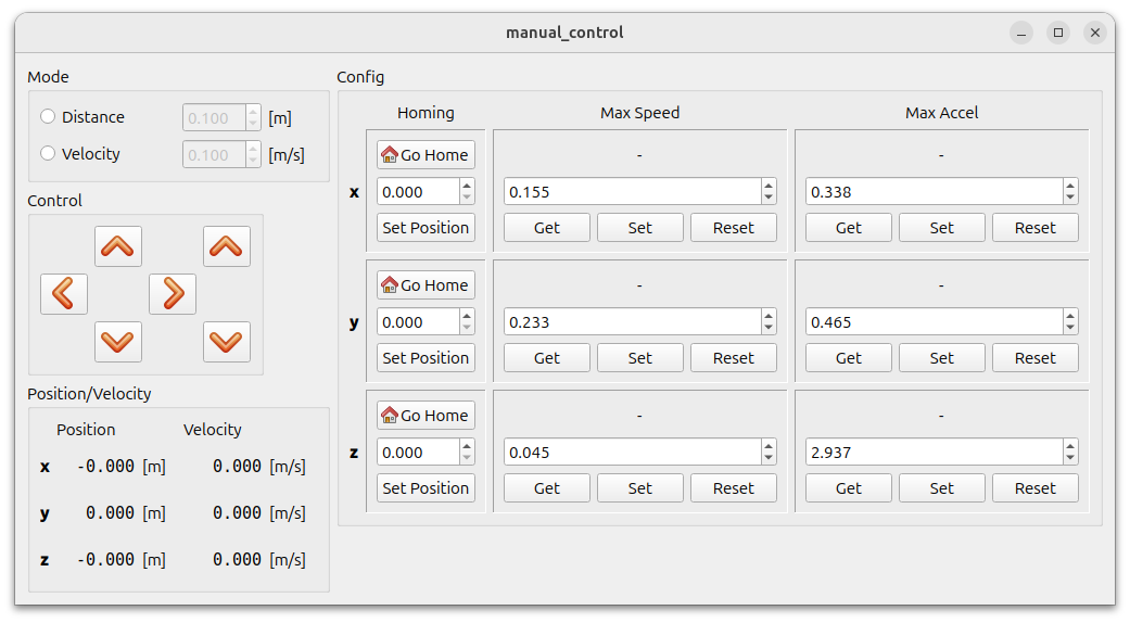
A window should open:
Fig. 5 Gantry GUI for manual control.
Remember to home the motors before using them.
Before you can use the manual control, you need to set a mode:
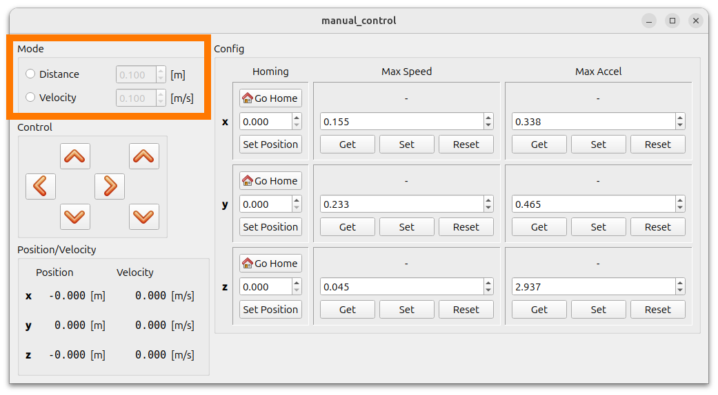
Fig. 6 Mode selection: manually control either distance travelled or velocity of motors.
Then, you can use the arrows to control the individual axes.
Closing the GUI: Ctrl + C + you will need to manually close the window.
Waypoint Grid Control
For measurements, you might want to position the gantry system at a certain set of waypoints. We have an example implementation for this within our gantry ROS2 package.
Run (preferably on your own laptop):
$ ros2 launch gantry waypoint_grid_control_node.launch.py
To start the waypoint controller, call the start service:
$ ros2 service call /gantry/gantry_grid_control/start std_srvs/srv/Trigger
requester: making request: std_srvs.srv.Trigger_Request()
response:
std_srvs.srv.Trigger_Response(success=False, message='Starting...')
To stop:
$ ros2 service call /gantry/gantry_grid_control/stop std_srvs/srv/Trigger
requester: making request: std_srvs.srv.Trigger_Request()
response:
std_srvs.srv.Trigger_Response(success=True, message='Stopping...')
Important
The gantry GUI should not be running at the same time!
By default, the waypoints are defined within the file gantry/config/waypoint_grid.yaml. Adapt the waypoints by e.g. writing your own script.
On your own laptop, you can simply edit the default waypoint file. Alternatively, define the path to your waypoint file by using the waypoint_file launch argument.
Restart Gantry System
The Raspberry Pi should be shutdown before the power gets removed. Run
sudo shutdown 0on the pi and wait until its green LED is not blinking anymore.Remove power from gantry system: Press any of the red emergency buttons.
To restart, all emergency buttons need to be enabled again. For this, they should all look like the button on the left:
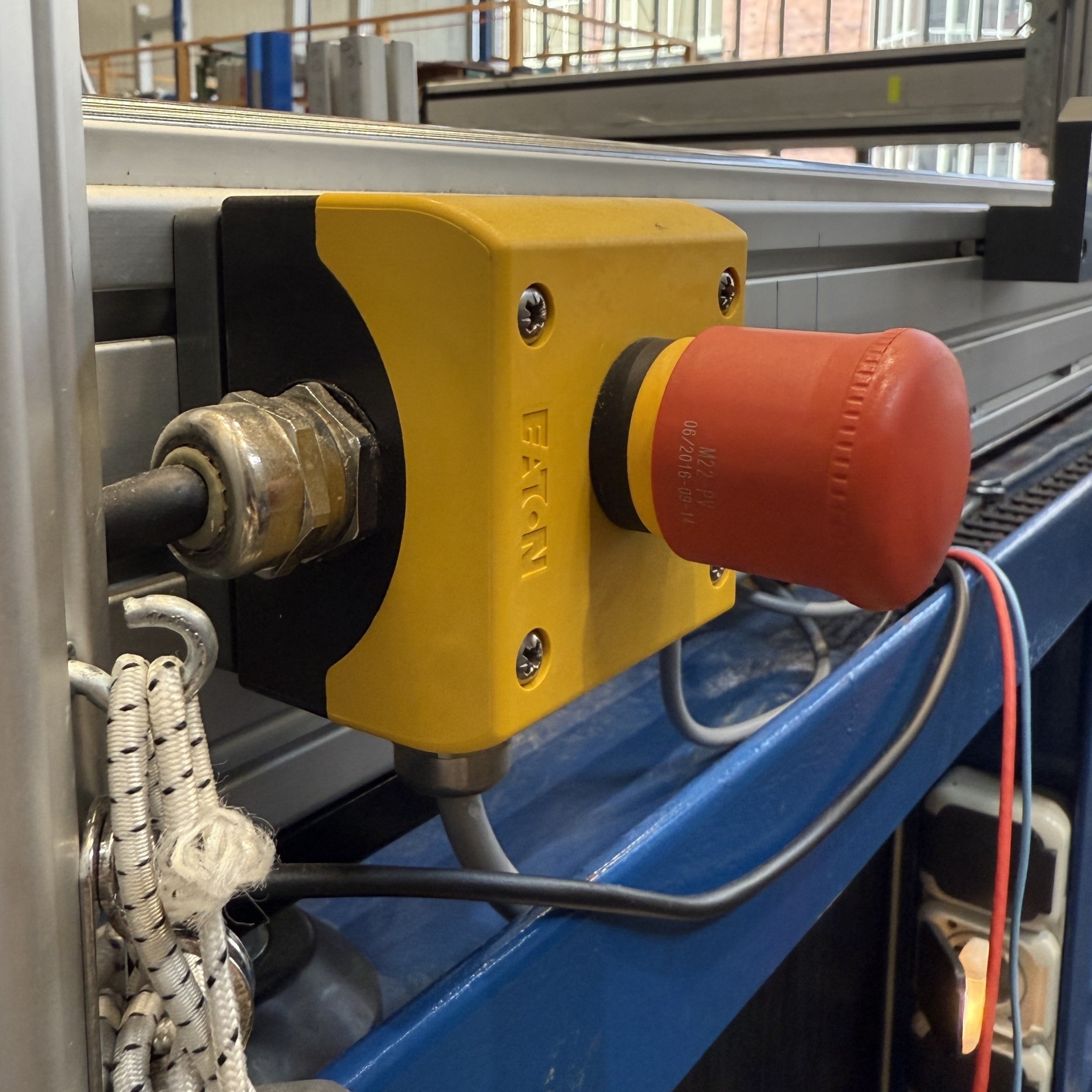
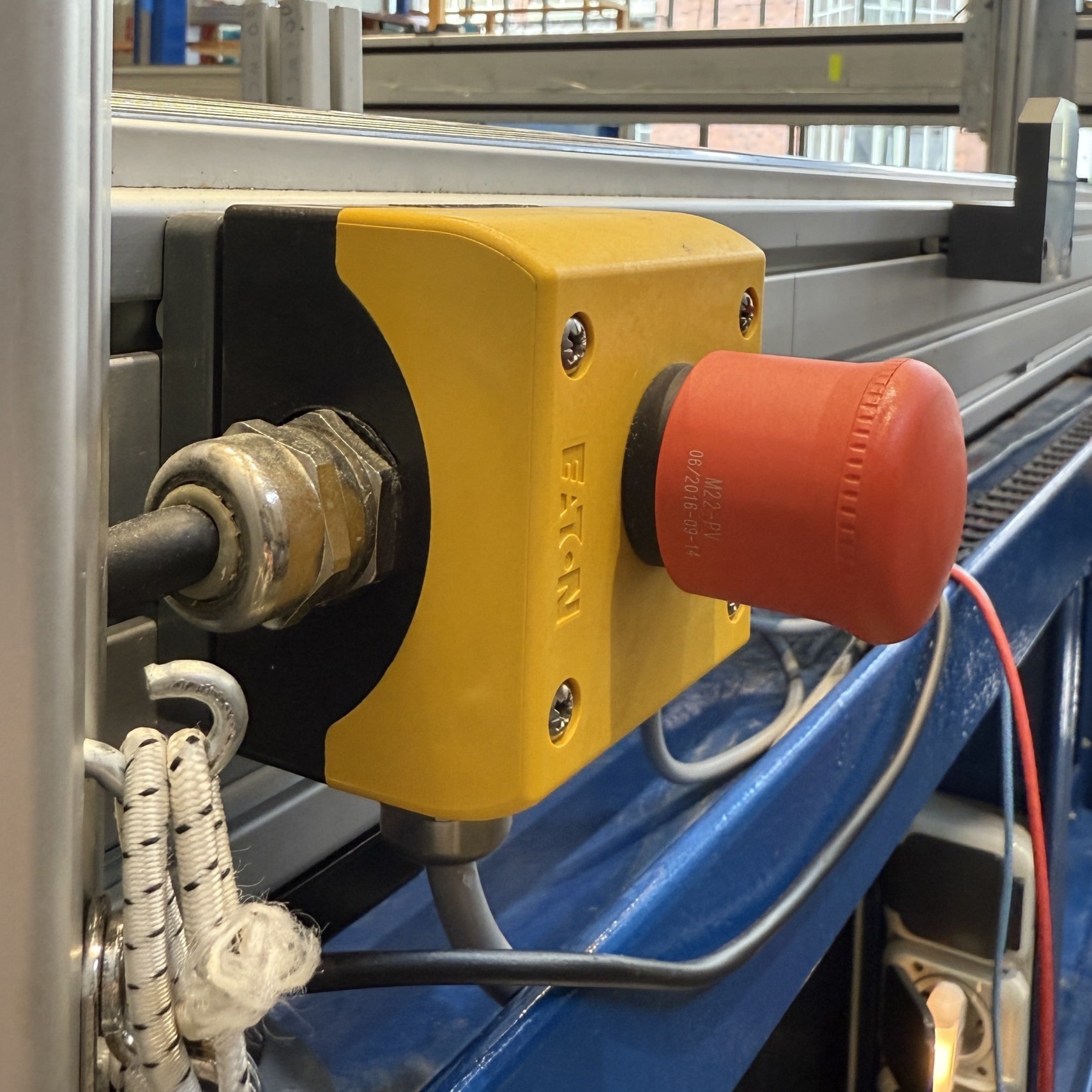
Not pressed button (left) and pressed button (right).
To turn on power again, press this button within the gantry power supply box:

Fig. 7 Power button for gantry system.
When powered, the green LED should be on.
Important
You need to re-home the motors any time the power has been shut off. This is crucial!
Note
When the power is off, the x-axis and the y-axis can be moved by hand.